Double-bow Shoelace Device
Patent Number: US 6,571,437 B2
The double-bow shoelace device, invented by Kun-Chung Liu, is used to cinch two ends of a shoelace together. The parts involved in the device are a shoelace, a clamp member used to cinch the laces, and a positioning unit used to form the bow on top of the clamp member. We are interested in the clamping member of this device because it has the ability to fasten together two ends of string or suture without the need for a knot. The two ends of lace are fed through and pinched within the clamping member by a spring action. The depressible spring-activated clamping member allows for the ability to adjust where the fastener is applied along the string, so that the length of the chord formed by both strings can be adjusted.
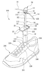
The double-bow shoelace device is used with a shoe that has laces coming out of eyelet tabs on either side of a tongue. For the explanation of this device, the shoelace is thought of in three separate sections. The lower section of lace weaves back and forth between the eyelets to form a crisscross pattern. The upper sections of lace are tied together in a knot with the distal lace ends hanging from the knot. The middle section includes the stretch of lace that extends from each of the eyelet tabs up to the knot. The clamp member is positioned on this middle stretch of lace – above the eyelets and below the knot. The clamp slides along this middle section to tighten or loosen the shoe. Sliding the clamp down the laces pulls the lower sections of the laces closer together, tightening the shoe. Sliding the clamp up the laces allows the lower sections of laces to separate from one another, loosening the shoe. The positioning unit is connected to the clamp member and to the knot. As the positioning unit is pulled down, it positions the knot on top of the clamp member and pulls the middle sections of lace in to form two loops between the knot and the clamp member. The entire design is shown in Figure 15.
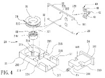
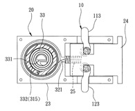
Detailed diagrams of the clamp member are shown below in Figures 16 and 17. The member includes an elongate casing (23), a clamping block (24), and a biasing member (25). The elongate casing (23) has a lower base (21) and a cover plate (22). The lower base includes a reel accommodating portion (213), a lace retention portion (216), and a channel between the two portions (219). The two posts (213 and 214) in the reel accommodating portion make a groove (215) for the positioning unit (30) to fit securely within. The clamping block (24) fits into the lateral opening of the lace retention portion (217). The middle portions of shoelace (10) run through the grooves formed by the holes in the lace retention portion (218 and 224) and the holes in the clamping block (243). The laces then run up through the holes in the cover plate (222). The biasing member (25) is a spiral spring that extends into the positioning hole and pushes the clamping block towards the open lateral side of the lace retention portion, thus pinching the laces within the grooves.
The double-bow shoelace device, invented by Kun-Chung Liu, is used to cinch two ends of a shoelace together. The parts involved in the device are a shoelace, a clamp member used to cinch the laces, and a positioning unit used to form the bow on top of the clamp member. We are interested in the clamping member of this device because it has the ability to fasten together two ends of string or suture without the need for a knot. The two ends of lace are fed through and pinched within the clamping member by a spring action. The depressible spring-activated clamping member allows for the ability to adjust where the fastener is applied along the string, so that the length of the chord formed by both strings can be adjusted.
The double-bow shoelace device is used with a shoe that has laces coming out of eyelet tabs on either side of a tongue. For the explanation of this device, the shoelace is thought of in three separate sections. The lower section of lace weaves back and forth between the eyelets to form a crisscross pattern. The upper sections of lace are tied together in a knot with the distal lace ends hanging from the knot. The middle section includes the stretch of lace that extends from each of the eyelet tabs up to the knot. The clamp member is positioned on this middle stretch of lace – above the eyelets and below the knot. The clamp slides along this middle section to tighten or loosen the shoe. Sliding the clamp down the laces pulls the lower sections of the laces closer together, tightening the shoe. Sliding the clamp up the laces allows the lower sections of laces to separate from one another, loosening the shoe. The positioning unit is connected to the clamp member and to the knot. As the positioning unit is pulled down, it positions the knot on top of the clamp member and pulls the middle sections of lace in to form two loops between the knot and the clamp member. The entire design is shown in Figure 15.
Detailed diagrams of the clamp member are shown below in Figures 16 and 17. The member includes an elongate casing (23), a clamping block (24), and a biasing member (25). The elongate casing (23) has a lower base (21) and a cover plate (22). The lower base includes a reel accommodating portion (213), a lace retention portion (216), and a channel between the two portions (219). The two posts (213 and 214) in the reel accommodating portion make a groove (215) for the positioning unit (30) to fit securely within. The clamping block (24) fits into the lateral opening of the lace retention portion (217). The middle portions of shoelace (10) run through the grooves formed by the holes in the lace retention portion (218 and 224) and the holes in the clamping block (243). The laces then run up through the holes in the cover plate (222). The biasing member (25) is a spiral spring that extends into the positioning hole and pushes the clamping block towards the open lateral side of the lace retention portion, thus pinching the laces within the grooves.
Detailed diagrams of the double-bow shoelace device