Neochord Device Patent
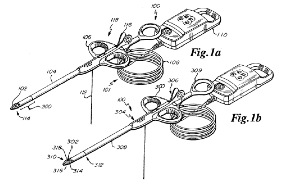
Neochord, Inc. has a pending patent (US 2009/0105751) for a device designed to perform minimally invasive repair of a valve leaflet in a beating heart. The Neochord device, invented by John Zentgraf, is an existing solution to deliver and implant artificial chordae tendineae to the mitral valve leaflet and is likely the most promising current solution. The device is pictured in Figure 9 and below in Figures 10 through ___. It is comprised of a handle assembly (300), a capture assembly (302), and a needle assembly (138). The handle is designed to maneuver the device within the patient’s chest cavity, the capture assembly is designed to capture a valve leaflet between distal and proximal tip portions, and the needle is designed to penetrate the valve leaflet and pull suture through the puncture. Additionally, a capture confirmation system (101) verifies successful capture of the leaflet.
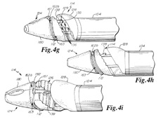
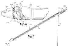
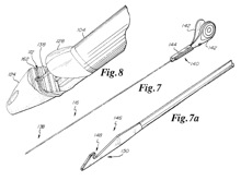
An actuator (309) is positioned on the proximal end of the handle and a shaft (308) extends from the distal end of the handle. The shaft has a circular cross-section so it can be smoothly inserted into an incision in the lower portion of the left ventricle underneath the mitral valve. At the end of the shaft is the clamping mechanism (314) that is operated by the actuator. The clamping mechanism is designed much like a jaw – it is made up of two separate components (316 and 318) whose inside surfaces fit tightly together. In the more detailed diagrams below, the lower clamp jaw (124) and the upper clamp jaw (128) are shown to form a tapered tip (180). When the actuator mechanism is activated, space is created between the two jaw components. The clamping jaw can then be positioned so that the leaflet is between the jaw components. Because the device enters from the bottom of the left ventricle, the lower clamp jaw clamps the leaflet from above and the upper clamp jaw clamps the leaflet from below. The leaflet capture verification monitor (110) on the capture confirmation system (101) indicates when the leaflet is securely captured within the clamp.
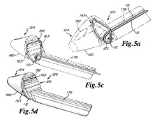
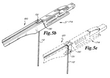
The suture deployment device (118) is comprised of a suture cartridge (102), a shaft (104), a handle (106), and a needle assembly (116). A preloaded suture cartridge (120) is contained in the shaft. It is comprised of a tapered lower clamp jaw (124), a suture (112), a suture retention system (130), a handle interface (174), a channel (131), and a groove on the clamp surface (162). The suture runs down the grooves (178) in the shaft to the distal end, where it weaves through the grooves (162 and 163) in the lower clamp jaw. The suture thereby forms a loop on the lower clamp jaw and then doubles back on itself to travel back up the shaft and back out the retention system. Note that the grooves have a depth approximately equal to the diameter of the suture.
The needle assembly also runs along the shaft and is comprised of a needle (138), a needle handle (140), and a needle head (146). The needle head has a notch (148), which is approximately equal in size to the diameter of the suture, and a hook (150). The needle handle includes finger tabs (142) and a needle carriage (144) that can slide along the top of the shaft. As the needle carriage is guided along the shaft, the needle head slides out from where it is contained within the upper clamp jaw. It pierces through the leaflet and enters the lumen (182) in the lower clamp jaw. It then hooks onto the loop of suture wound within the groove in the lower clamp jaw just beneath the lumen. The needle is then guided back through the leaflet, pulling the loop of suture through the puncture in the leaflet. The needle is pulled back all the way down the shaft, pulling the suture along with it, until it exits the device outside of the heart. The clamping jaw is then removed from the leaflet and the shaft and clamp assembly are removed from the left ventricle. As the device is removed from the heart, the suture, which is looped through the puncture in the leaflet, winds out from the shaft. Once outside of the heart, the suture strands are cut from the clamping assembly. The loose suture ends are then strung through the looped end of suture that was pulled out using the needle. The suture ends are pulled through this loop until the suture is tight around the leaflet.
An actuator (309) is positioned on the proximal end of the handle and a shaft (308) extends from the distal end of the handle. The shaft has a circular cross-section so it can be smoothly inserted into an incision in the lower portion of the left ventricle underneath the mitral valve. At the end of the shaft is the clamping mechanism (314) that is operated by the actuator. The clamping mechanism is designed much like a jaw – it is made up of two separate components (316 and 318) whose inside surfaces fit tightly together. In the more detailed diagrams below, the lower clamp jaw (124) and the upper clamp jaw (128) are shown to form a tapered tip (180). When the actuator mechanism is activated, space is created between the two jaw components. The clamping jaw can then be positioned so that the leaflet is between the jaw components. Because the device enters from the bottom of the left ventricle, the lower clamp jaw clamps the leaflet from above and the upper clamp jaw clamps the leaflet from below. The leaflet capture verification monitor (110) on the capture confirmation system (101) indicates when the leaflet is securely captured within the clamp.
The suture deployment device (118) is comprised of a suture cartridge (102), a shaft (104), a handle (106), and a needle assembly (116). A preloaded suture cartridge (120) is contained in the shaft. It is comprised of a tapered lower clamp jaw (124), a suture (112), a suture retention system (130), a handle interface (174), a channel (131), and a groove on the clamp surface (162). The suture runs down the grooves (178) in the shaft to the distal end, where it weaves through the grooves (162 and 163) in the lower clamp jaw. The suture thereby forms a loop on the lower clamp jaw and then doubles back on itself to travel back up the shaft and back out the retention system. Note that the grooves have a depth approximately equal to the diameter of the suture.
The needle assembly also runs along the shaft and is comprised of a needle (138), a needle handle (140), and a needle head (146). The needle head has a notch (148), which is approximately equal in size to the diameter of the suture, and a hook (150). The needle handle includes finger tabs (142) and a needle carriage (144) that can slide along the top of the shaft. As the needle carriage is guided along the shaft, the needle head slides out from where it is contained within the upper clamp jaw. It pierces through the leaflet and enters the lumen (182) in the lower clamp jaw. It then hooks onto the loop of suture wound within the groove in the lower clamp jaw just beneath the lumen. The needle is then guided back through the leaflet, pulling the loop of suture through the puncture in the leaflet. The needle is pulled back all the way down the shaft, pulling the suture along with it, until it exits the device outside of the heart. The clamping jaw is then removed from the leaflet and the shaft and clamp assembly are removed from the left ventricle. As the device is removed from the heart, the suture, which is looped through the puncture in the leaflet, winds out from the shaft. Once outside of the heart, the suture strands are cut from the clamping assembly. The loose suture ends are then strung through the looped end of suture that was pulled out using the needle. The suture ends are pulled through this loop until the suture is tight around the leaflet.
Detailed drawings of the Neochord clamping jaw and
Neochord needle and suture assemblies