Valve to Myocardium Tension Members Device and Method
Patent Number: US 6,332,893 B1
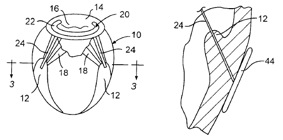
This device, invented by Todd J. Mortier and Cyril J. Schweich Jr., is used for heart valve repair, specifically mitral valve repair. Figure 20 shows a cross section view of the left ventricle on the left and a close up view of the configuration of the device on the right. The device includes at least one elongate tension member (24) with a basal anchor on one end and a secondary anchor on the other. The basal anchor is anchored next to the mitral valve. In Figure 20, the basal anchor (20) is depicted as an annuloplasty or suture ring sewn around the annulus. The basal anchor could also be an artificial heart valve for patients with severely deteriorated mitral valves. The secondary anchor is anchored at a location away from the valve; it is typically anchored to a papillary muscle (12) or transmurally anchored. The secondary anchor could be a hook-shaped loop sewn through the papillary muscle tissue, a screw-shaped tissue anchor, or a transmural anchor pad. Figure ___ shows the tension member extending transmurally and attaching to a pad (44) secured against the outer wall of the left ventricle. The positioning of the second anchor is chosen such that the tension member alters the geometry of the left ventricle in order to reduce wall tension on the valve leaflets. By reducing tension on the leaflets, tension in the chord is altered as well. The tension member can be designed to be as rigid or as flexible as necessary. Additionally, a second tension member can be positioned across the ventricle, perpendicular to the first tension member, to further reduce wall stress. Additionally, as with the previous device, this device could shrink the annulus of the mitral valve to reduce regurgitation.
This device, invented by Todd J. Mortier and Cyril J. Schweich Jr., is used for heart valve repair, specifically mitral valve repair. Figure 20 shows a cross section view of the left ventricle on the left and a close up view of the configuration of the device on the right. The device includes at least one elongate tension member (24) with a basal anchor on one end and a secondary anchor on the other. The basal anchor is anchored next to the mitral valve. In Figure 20, the basal anchor (20) is depicted as an annuloplasty or suture ring sewn around the annulus. The basal anchor could also be an artificial heart valve for patients with severely deteriorated mitral valves. The secondary anchor is anchored at a location away from the valve; it is typically anchored to a papillary muscle (12) or transmurally anchored. The secondary anchor could be a hook-shaped loop sewn through the papillary muscle tissue, a screw-shaped tissue anchor, or a transmural anchor pad. Figure ___ shows the tension member extending transmurally and attaching to a pad (44) secured against the outer wall of the left ventricle. The positioning of the second anchor is chosen such that the tension member alters the geometry of the left ventricle in order to reduce wall tension on the valve leaflets. By reducing tension on the leaflets, tension in the chord is altered as well. The tension member can be designed to be as rigid or as flexible as necessary. Additionally, a second tension member can be positioned across the ventricle, perpendicular to the first tension member, to further reduce wall stress. Additionally, as with the previous device, this device could shrink the annulus of the mitral valve to reduce regurgitation.
Tension member extending from the mitral valve to the myocardium of the left ventricle